Fundamentals and Practices of Sensing Technologies
by Dr.
Keiji Taniguchi, Hon. Professor of
Xi’ an
Dr. Masahiro Ueda, Honorary
Professor, Faculty of Education and Regional Studies
Dr. Ningfeng Zeng, an
Engineer of Sysmex Corporation
(A Global Medical
Instrument Corporation),
Dr. Kazuhiko Ishikawa,
Assistant Professor
Faculty of Education and
Regional Studies,
[Editor’s
Note: This paper is presented as Part IX of a series from the new book
“Fundamentals and Practices of Sensing Technologies”; subsequent chapters will
be featured in upcoming issues of this Journal.]
Chapter Five – Part I
Abstract for Chapter 5
In chapter 4, we have
described same applications of measurement technologies by means of laser
attenuation to manufacturing plant. In this chapter, same applications of
measurement technologies by means of laser reflection were described. That is,
a color sensor for dispersive dye is described in 5.1, a counter sensor for
cloth weft in 5.2, a vibration sensor for speaker surface in 5.3, a torsion
sensor in power transmission shaft in 5.4, a diameter sensor for polyethylene
filament in 5.5, a displacement and vibration sensor for the pipe in 5.6, a
cross-linking sensor for enamel on a copper wire in 5.7, a surface creases
sensor for polyethylene sheets in 5.8, a surface displacement sensor in 5.9, a
hybrid sensor for the surface displacement in 5.10, a thickness sensor for
glass bottle in 5.11, and a thickness sensor for film in 5.12.
5.1 Color Sensor for
Dispersive Dye
5.1.1 Introduction
We have previously
reported on the real-time optical measuring method1) and the
monitoring system2) for dye color and concentration for ionic dye,
i.e., water-soluble dye. In this case, a light attenuation method can be
effectively applied since the light intensity passing through the dye decreases
exponentially as dye concentration increases up to a range of practical
concentration.
On the contrary, the
light intensity decreases within an extremely small concentration range for a
dispersive dye, i.e., an oil dye which is mainly used for a synthetic fiber. It
is, therefore, necessary to dilute dye of practical concentration to a
reasonable concentration. This gives up a real-time detection which is
indispensable in a dyeing process. Our new method enables real-time detection.
The oil dye has roughly
a spherical shape and is suspended in water with hydrophobia agent. It is then
considered that the light intensity scattered on the dye sphere increases as
the dye concentration increases. That is, the scattered light intensity may be
applied for the measurement of the oil dye concentration. We call this "
the light scattered method".
In this section, the
principle and the experimental result of the light scattered method are
described, and the flexibility of the sensor is discussed from the viewpoint of
practical use.
5.1.2 Principle and
Method
The mathematical
principle of the method is the same as used previousy.2) That is,
three unknown parameters, i.e., each concentration of three base color dyes,
can be determined by solving a simultaneous cubic equations with three unknowns-but
the method is physically quite different from the previous one, i.e., the
scattered light intensity is used for three known parameters in this case. A
transmitted light intensity was used for the known parameters in the previous
method and an exponential function can be applied between incident and
transmitted light intensities for ionic dye. Tailor expansions, however, must
be used for oil dye since part of the relations is complicated, the reason of
which will be discussed in section 3. Thus, the method is, mathematically, applicable
for popular use.
Fig. 5.1 shows the
principle of the method. Laser light containing the three base colors (red, ![]() R; green,
R; green, ![]() G; blue,
G; blue, ![]() B) is guided into a measuring cell, in which three
base colors of oil dye (red, CR; yellow, CY; blue, CB)
are suspended. The oil dye scatters light on the surface.
B) is guided into a measuring cell, in which three
base colors of oil dye (red, CR; yellow, CY; blue, CB)
are suspended. The oil dye scatters light on the surface.
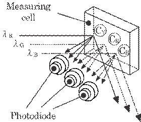
Fig. 5.1
Optical principle of the method. Part of the incident light of three
base colors is scattered from an oil dye consisting of the three base dye
colors.
The
scattered light intensity, Id, is expressed by a Tailor expansion as
follows:
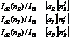
|
|
(5.1) |
where
Ii shows the incident intensity of the laser light, n the
concentration of the oil dye and Ki(i=0,1,2,3,...) the scattering
coefficient in a broad sense. In particular, K0 shows the scattered
light intensity from a glass plate and pure water without dye. It is obvious
from a physical point of view that Id increases linearly with
increasing dye concentration, n, if it is reasonably diluted. However, the
relation between scattered light intensity and the dye concentration is not so
simple in practice, as shown later (Fig. 5.4(b)). It depends not only on the
dye concentration but also on a combination of dye color and wavelength of the
laser light.
The basic relation
between scattered light intensity Id and dye concentration n(nR,nY,nB)
is concretely expressed as follows:
|
|
(5.2) |
Where
IiR and IdR show an incident and a scattered laser light
intensities of wavelength ![]() R, j= 0,1,2 and 3, and the matrices [a]and[nj]are
expressed as follows:
R, j= 0,1,2 and 3, and the matrices [a]and[nj]are
expressed as follows:
|
|
|
|
|
|
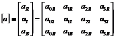


Where
[a] shows a scattered coefficient in a broad sense, as shown in Eq. (5.1). The
same relations are given for the laser light of wavelength ![]() G by replacing [a] with [b], and IdR and
IiR with IdG and IiG, and ,also, for the laser
light of wavelength
G by replacing [a] with [b], and IdR and
IiR with IdG and IiG, and ,also, for the laser
light of wavelength ![]() B by replacing [a] with[c], and IdR and
IiR with IdB and IiB. These 36 scattering
coefficients were determined by the method of least squares from nine relations
between scattered light intensity and dye concentration obtained experimentally.
B by replacing [a] with[c], and IdR and
IiR with IdB and IiB. These 36 scattering
coefficients were determined by the method of least squares from nine relations
between scattered light intensity and dye concentration obtained experimentally.
The scattered light
intensity from mixed dye may be superposed of each light intensity from three
color dyes. This is indispensable to our method and is realized within a
reasonable range of dye concentration, as shown in Fig. 5.3. That is, the expressions
for this superposition principle can be shown as follows;
|
|
(5.3) |

The
left-hand terms in these equations are the total light intensities from the oil
dye mixed with three base colors and then the known quantities. On the right-hand
side, the unknown quantities, i.e., the dye concentrations n(nR, nY,
nB), are contained in the form of Eq.(5.2). The equation can be
solved by the Levenberg-Marquardt-Morrison's method.3)
Figure 5.2 shows the
system for the measurement. A semiconductor laser was used for red light of
wavelength ![]() R=670 nm and a multiline Ar ion laser was used for
green and blue lights of wavelengths
R=670 nm and a multiline Ar ion laser was used for
green and blue lights of wavelengths ![]() G=515 nm and
G=515 nm and ![]() B=458 nm, respectively. The output intensity of
the laser light scattered from the oil dye filled in the cell was measured on a
photodiode and converted to an electric signal. The signal was amplified,
sampled and digitized in 12 bits. The maximum sampling frequency of the data
acquisition was limited to about 1 kHz by the A/D converter. The digitized
signal was used to obtain the relations between the scattered laser light
intensity and the dye concentration. The 36 scattering coefficients were
obtained by the method of least squares from these relations and were used in
Eq. (5.3) to calculate the concentration. The results were displayed on the
monitor. All the data in this calculation were obtained by averaging 80
samples.
B=458 nm, respectively. The output intensity of
the laser light scattered from the oil dye filled in the cell was measured on a
photodiode and converted to an electric signal. The signal was amplified,
sampled and digitized in 12 bits. The maximum sampling frequency of the data
acquisition was limited to about 1 kHz by the A/D converter. The digitized
signal was used to obtain the relations between the scattered laser light
intensity and the dye concentration. The 36 scattering coefficients were
obtained by the method of least squares from these relations and were used in
Eq. (5.3) to calculate the concentration. The results were displayed on the
monitor. All the data in this calculation were obtained by averaging 80
samples.
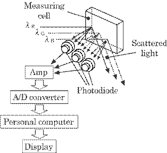
Fig. 5.2 Optics and sensor system.
5.1.3 Experimental
Results and Discussions
We
performed first of all, an experiment to confirm the superposition principle.
Figure 5.3 shows the result. As is shown, the scattered light intensity from
the mixed oil dye almost equals the sum of light intensities from each color of
dye. The relation, however, can be realized only in the limited range of
concentration up to about 0.01 g/l. The concentration of 0.01 g/l is slightly
insufficient for a practical dye concentration used in dye process. This is the
only one weak point of our method. The actual sensitivity of the method depends
on this accuracy of the superposition principle. However, the small change of
dye concentration in the neighborhood of practically used concentration may be
detected with high sensitivity by this method, which is discussed bellow. This
seems to be most important in practical use.
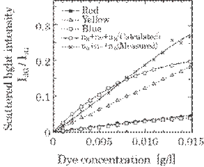
Fig. 5.3 Scattered light (wavelength of 670 nm)
intensity from each color of dye concentration and the one for mixed dye
concentration with a theoretical intensity.
Figures 5.4(a) and (b)
show examples of the relation between scattered light intensity and dye
concentration. Figure 5.4(a) shows an example of a simple relation and 5.4(b) a
relatively
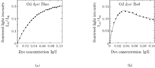
Fig. 5.4 Scattered light intensity for dye
concentration: (a) for laser light of wavelength ![]() R=670 nm and for blue dye; (b)
R=670 nm and for blue dye; (b) ![]() B=458 nm and red dye.
B=458 nm and red dye.
complicated
one. In figure 5.4(a), it is naturally considered, in the diluted dye, that the
scattered light intensity increases linearly as the number of dye particles in
the unit volume increases, i.e., dye concentration, n. The light intensity,
however, may become proportional to n2/3 since the scattered light
from inner area cannot pass through the dye cell to the photodiode due to a
screening effect of the outer particles, and then the effective scattered light
into the photodiode results from only an extremely thin layer of the surface.
In figure 5.4(b), on the contrary, the complexity may be caused by the
scattering and absorption of laser light on the dye particle. However, it can
easily be fitted to the experimental results with high accuracy by using a
Table 5.1 shows all the
coefficients. The coefficients independent of the dye concentration, i.e., a0,
b0 and c0, have to be one essentially, as seen in Eq.
(5.1) and almost equal to one practically as shown in this table.
Table 5.1 Scattering coefficients obtained from
the relation between the scattered light intensity and the dye concentration by
the least squares method for all combinations of light colors and dye colors.
|
|
C |
Scattering
coefficient |
|||
|
j=0 |
j=1 |
j=2 |
j=3 |
||
|
|
ajR |
1.2015 |
205.49 |
171.41 |
-4998.2 |
|
|
ajY |
1.0056 |
99.099 |
306.93 |
-1964.3 |
|
|
ajB |
1.0665 |
106.51 |
-1068.4 |
3930.5 |
|
|
bjR |
1.0270 |
29.693 |
-144.21 |
2100.3 |
|
|
bjY |
0.84900 |
184.24 |
-1224.6 |
2855.9 |
|
|
bjB |
1.0246 |
28.167 |
-314.25 |
1162.4 |
|
|
cjR |
1.0573 |
21.224 |
-330.86 |
1426.9 |
|
|
cjY |
1.0703 |
37.943 |
-599.78 |
2970.7 |
|
|
cjB |
1.0180 |
21.583 |
-191.84 |
577.36 |
The experiment of
increasing each color dye successively was carried out to confirm the
reliability of the method. The dye concentration in the cell filled with pure
water was increased successively by the droplets of high concentration dye.
Figure 5.5(a) and (b) show examples of the calculated concentration from Eq.
(5.3) and the theoretical one for blue and red dye, respectively. The
experimental sensitivity is restricted to the error between calculated and
theoretical concentrations. It can be seen that the experimental sensitivity is
about 1 mg/l, which is sufficient for practical use.
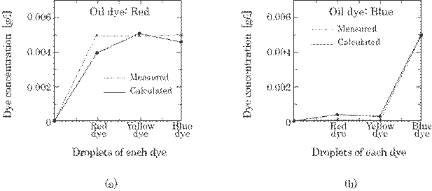
Fig. 5.5 Calculated dye concentration and the
real one, i.e., theoretical concentration, for the droplets of each dye into the
water: (a) for red dye; (b) for blue dye.
As discussed above, the
reliability of this method is based on the fact that the superposition
principle is realized. The concentration range of high accuracy is between 0
and 20 mg/l, which is inadequate in practical use. However, the small change of
dye concentration ![]() n around the practically used concentration n0 due
to the small change of scattered light intensity
n around the practically used concentration n0 due
to the small change of scattered light intensity ![]() Id can be calculated by using the differential coefficient
of the graphs in Fig. 5.3, (Id)'n=n0. Since the relation
between scattered light intensity Id and the dye concentration n can
be expressed as in Eq. (5.2),
Id can be calculated by using the differential coefficient
of the graphs in Fig. 5.3, (Id)'n=n0. Since the relation
between scattered light intensity Id and the dye concentration n can
be expressed as in Eq. (5.2), ![]() n can be expressed as follows,
n can be expressed as follows,
|
|
(5.4) |
In
this sense, Fig. 5.5 shows the results around n=0.
In conclusions, the
following results were obtained.
(1) The method is based on the principle of light
scatter and is then applicable for dispersive dyes and so on.
(2) The sensitivity of the method was about 1
mg/l and may be satisfactory for dyeing machines presently on the market.
(3) The system can then be effectively used for
monitoring or detecting a small change of dye concentration.
5.2 Counter Sensor for
Cloth Weft
5.2.1 Introduction
In the textile industry,
two major parameters are left to be studied in the production process, the
cloth length and the cloth weft density which is given by a weft numbers per
unit length. The former is the business basis between a seller and a buyer, and
the latter determines aspect of the cloth, soft or rough. The length of the
cloth changes with the tension and the history after weaving such as the stored
time and the stored condition. Those two parameters can be precisely determined
by counting the weft number and measuring the cloth length simultaneously.
Since the weft density is given in the weaving process, the cloth length can be
determined by measuring the weft number.
The purpose of this
study is to improve the previously reported system4) for an industrial
use. The present system provides a good accuracy and a high counting speed
enough for various types of knitting machines.
5.2.2 Method and System5)
We have proposed the
light attenuation method4) for counting cloth weft number by means
of light passed through the cloth. In this system, a light source and a light
receiver were set up on the opposite side of the cloth. Then, this method can
be effectively used only when the cloth is thin and light passes through the
cloth with a little attenuation.
On the contrary, the
principle of the present method is based on the light scattering on the cloth.
The method can then be applied to a thick cloth such as a light shielding
curtain as well as a thin cloth. Further, it can be also applied to the cloth
of a different Moire appearance of head and tail, to which the light
attenuation method cannot be applied. The light scattering method can, thus, be
widely applied. The method, further, has an advantage over the light
attenuation method from a practical point of view, that the sensor head
including both light source and light receiver can be incorporated in a body
since they are set up on a same side to the cloth.
Fig. 5.6 shows a sensor
head (a) and a whole system (b) of the method. A sheet-like laser light illuminates
the cloth with parallel to a Moire appearance of the cloth as shown in Fig.
5.6(a). The scattered laser light is received by a PIN photodiode. A difference
in direction between the sheet-like laser light and the Moire appearance
line(for short "Moire line") may cause a complicated wave form of the
received intensity and then yield a count error of the Moire line number. This
will be discussed in 5.2.4. The output signal of the photodiode is then led
into a counter system consists of an amplifier, digitizer(called ![]() V detector) and counter. The
V detector) and counter. The ![]() V detector reforms sine-like wave form to a square waves. The
Moire line can then be
V detector reforms sine-like wave form to a square waves. The
Moire line can then be
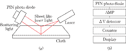
Fig. 5.6 Experimental system. (a) Sensor head and (b)
Signal processing system.
exactly
countered and then expressed on the display. Thus, the method in this paper is
fundamentally to count the Moire lines. The sine-like wave results only from
the Moire appearance of the cloth surface and does not depend on the speed of
cloth motion. This may be one of the merits over other methods.
The weft density and the
Moire density are usually different. There is, however, a definite relation
between them depending on the weaving manners, such as plain weave, twill weave
and sateen weave. We can then determine the weft number from the Moire line
number.
5.2.3 Experimental
Results5)
Figure 5.7 shows
representative examples of the clothes having various Moire appearance. This
Moire appearance results from the strength of the scattered light intensity due
to an uneven cloth surface and yields sine-like wave for the output signal on
the PIN photodiode. In each of the photograph, the left-hand side photographs
show the head of the cloth and the right-hand side the tail. The black points
at the bottom in each photograph show a measurement for 1 mm length. The Moire
appearances of the head and tail in each cloth are quite different as shown in
this figure except for (a). These clothes are all knitted together with thick
thread bundled by some fine threads. The thick lines in each figure show the
laser light cross-sections irradiated on the cloth. The line must be parallel
to the Moire line, as much as we can, to obtain sine-like wave intensity. This
enables us count the Moire line numbers accurately. A slight difference in
directions between both lines may lead to a miscount of the Moire line numbers
as discussed in 5.2.4.
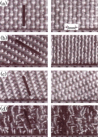
Fig.5.7 Photographs of the cloth samples. Left
shows the head and the right the tail. (a) Examples of plane weave, (b) twill
weave, (c) sateen weave, and (d) a towel.
Fig. 5.8 shows the
output signals of the scattered light intensity received by PIN
photodiode(upper side) and the square waves reformed by ![]() V detector(lower side). We have examined for ten kinds of
clothes and found out that the count error rate was below 1% for all clothes
with a few marked exceptions which have not a clear Moire appearance such as in
Fig. 5.7(d). We are now under study in this problem.
V detector(lower side). We have examined for ten kinds of
clothes and found out that the count error rate was below 1% for all clothes
with a few marked exceptions which have not a clear Moire appearance such as in
Fig. 5.7(d). We are now under study in this problem.
We have further examined
the system for the industrial use. The system was set up in a manufacturing
plant. Table 5.2 shows an example. The error between mean value and number of
Moire lines per unit length was found to be less than 1% in each measurement.
The speed of the cloth movement was 75m/min. The cloth used was the one
described in Fig. 5.7(b).
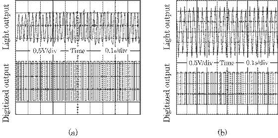
Fig.5.8 Wave form of the scattered laser light
intensity at the PIN photodiode (upper side) and the square waves reformed by ![]() V detector (lower side). (a) and (b) correspond to the
experimental results of (a) and (b) in Fig. 5.7. These results were obtained
where sheet-like laser is parallel to the cloth Moire line as shown 1 in Fig.
5.9 (a).
V detector (lower side). (a) and (b) correspond to the
experimental results of (a) and (b) in Fig. 5.7. These results were obtained
where sheet-like laser is parallel to the cloth Moire line as shown 1 in Fig.
5.9 (a).
Table 5.2 Measured numbers of cloth Moire line
in industrial use and count error rate from the mean value (Cloth speed:
75m/min).
|
Cloth length
(m) |
Number
of moire
line |
Moire
line number
in 1m |
Error
rate from mean
value (%) |
|
115 |
117878 |
1025.03 |
-0.78 |
|
120 |
124600 |
1038.33 |
0.51 |
|
117 |
120800 |
1032.48 |
-0.06 |
|
118 |
122000 |
1033.90 |
0.08 |
|
117 |
120300 |
1028.21 |
-0.47 |
|
118 |
121400 |
1028.81 |
-0.41 |
|
117 |
121900 |
1041.88 |
0.85 |
|
119 |
122600 |
1030.25 |
-0.27 |
|
117 |
121380 |
1037.44 |
0.42 |
|
117 |
120000 |
1025.64 |
-0.72 |
|
117 |
120580 |
1030.60 |
-0.24 |
|
117 |
121560 |
1038.97 |
0.57 |
|
116 |
120444 |
1038.31 |
0.51 |
|
Mean
value |
1033.07 |
|
|
The maximum counting
frequency was found to be above a few tens kHz in the best condition without
interpolation method discussed in section 5.2.4. It is limited by a processing
speed of the computer to interpolate a complicated wave-form to a sine-like
wave-form. Even in this case, it can be above 10 kHz.
5.2.4 Discussions
A. Improvement of the
Accuracy
The
accuracy of counting depends basically on the degree of the parallel between
both line directions of the sheet-like laser light on the cloth and of the
Moire appearance. Figure 5.9 shows a schematic diagram of this relation. The
cross-section of the sheet like laser light of width, w, and length, l,
illuminates the cloth of Moire line pitch p, where three cases 1,2 and 3 are
shown as the examples. It was found from the experiment that the high contrast
sine-like wave can be obtained when the width is between 1/2 and 1/3 of the
Moire line pitch, p, and the length is between 5 and 20 times of the width.
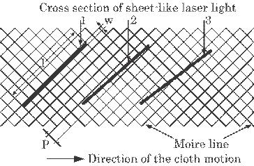
Fig. 5.9 A relation between directions of the
sheet-like laser light and the Moire line. 1 is a case of perfect parallelism,
2 a slight lack of parallelism and 3 a lack of parallelism.
Fig. 5.10 shows similar
waves to Fig. 5.8, which corresponds to the cross section of sheet-like laser
light in Fig. 5.9 (2). They are complicated in particular Fig. 5.10(b) as
compared to Fig. 5.8. An amplitude decrease of the sine-like waves may be due
to a slight decrease of parallelism between both lines as shown in Fig. 5.9 (2)
and (3). The slight decrease of parallelism is unavoidable in an industrial
application because of a twist of the Moire appearance caused by an unbalanced
tension of the cloth. It does not, however, cause a miscount since a correct
square waves are obtained as shown in Fig. 5.10(a). On the contrary, a large
distortion of the sine-like waves due to a lack of parallelism may cause a
miscount as shown in Fig. 5.10(b). But the lack of parallelism was found to be
rather small in the experiment at the manufacturing plant as shown in table
5.2. The distortion may, rather, be due to the lack of contrast of the Moire
appearance.
The problem of the
degree of parallelism may be easily solved by the use of the sheet-like laser
light with a short length. It was, however, found from the experiment that the
contrast of the scattered light intensity was also decreased. Thus, it is
essential to find a point of compromise between the length l and the pitch p.
This is, however, not an essential solution.
Three
essential methods may be considered to solve this problem. The first is to
reform the complicated wave form to a sine-like wave by the interpolation
method. This can be done by a software technique and may be simplest and
effective method from a practical point of view. The second is to use two PIN
photodiodes placed at different position. In this case, one photodiode may, at
least, receive a right sine-like wave even if the other receives a complicated
wave. The count is always done by a right sine-like wave using a OR-logic circuit.
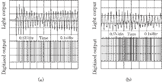
Fig. 5.10 Wave form of the scattered laser light
intensity and corresponding square wave form for the cloth in Fig. 2(c). (a)
shows a case where sheet-like laser is slightly inclined to Moire line as shown
2 in Fig. 4 and (b) rather inclined to Moire line as shown 3 in Fig. 4.
Thus, even if each
photodiode has a count error rate of 5%, both photodiodes may reduce a count
error rate to 0.25%(=0.05*0.05). The third is to adjust the laser light
direction parallel to the Moire line of the cloth by means of feedback system,
where a signal of a phase difference of the light intensity received on both
photodiodes is used to rotate slightly the direction of the laser mounted on a
rotary machine.
B. System for Industrial
Use
The sensor head is usually
fixed at a position and the cloth moves in an industrial use. It has, however,
to be moved when the cloth is at rest. Figure 5.11 is a proposed system
acceptable for these two purposes. The laser mounted on the belt is moved at a
constant speed by a motor drive when the cloth is at rest and is fixed at a
proper position when the cloth is moved. The laser and the PIN photodiode are
confined in a light shielding box to eliminate the back ground light noise.
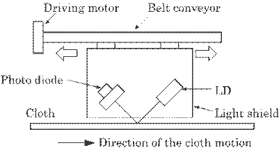
Fig. 5.11 Proposed
counter system for cloth weft number using laser light for industrial use.
In conclusions, the
following results were obtained.
(1)
This system can be applied to various kinds of clothes.
(2)
It can be applied to both cases, i.e., cloth is at rest and moved.
(3)
It's accuracy is above 99%.
(4)
It has a counting frequency of above 10 kHz.
5.3 Vibration Sensor for
Speaker Surface
5.3.1 Introduction
A sound speaker for a
high frequency of approximately 10 kHz is usually composed of thin mirror-like
metal plates. The efficiency of the speaker will be determined by the material,
thickness, and tension of the metal. In practice, however, efficiency is
determined by measuring the vibration amplitude due to an electric input power.
Therefore, in order to evaluate the speaker quality, it is important and urgent
to develop a practical method to measure the vibration of the micro-speaker
with radius about 5 mm.
Generally, a vibration
with amplitude above a few tens microns are measured by using a mechanical
method.6) Optical interferometry, in particular optical holography,7)
has been used to measure vibration with amplitude between 0.01 ![]() m and several microns. As to a vibration with amplitude about
10
m and several microns. As to a vibration with amplitude about
10 ![]() m as that of our speaker, Doppler method is probably the only
way to measure it. However, it is, in itself, a method to measure a velocity,
and a particular improvement in optical arrangement and electronic circuit is
necessary to use it as a detector for the vibration amplitude.8) The
system, therefore, is not simple and cost-effective for our case.
m as that of our speaker, Doppler method is probably the only
way to measure it. However, it is, in itself, a method to measure a velocity,
and a particular improvement in optical arrangement and electronic circuit is
necessary to use it as a detector for the vibration amplitude.8) The
system, therefore, is not simple and cost-effective for our case.
In this section, a
simple method through measuring the multi-reflected laser beam
"dispersion" due to vibration to measure vibration amplitude above 10
![]() m is proposed.
m is proposed.
5.3.2 Principle and
Method
The basic idea of the
proposed method is to use a plane mirror just on a vibrating speaker and to
cast a multi-reflected laser beam between them on the detectors such as a
screen and a CCD camera. The laser light reflected on the vibrating mirror
disperses and becomes obscure slightly at the edge of the laser beam. Actually,
the reflected laser beam is not dispersed but is deflected slightly from an
original direction due to the vibration, but it seems dispersed, as the
vibration frequency is so high as to detect it with eye and detector. We call
the phenomenon "a dispersion" in this study. The dispersion increases
linearly, according to the vibration amplitude; that is, the vibration
amplitude can be detected by means of the dispersion. The dispersion is,
however, usually very small. The multiple reflection increases the dispersion;
that is, multiple reflection leads to high sensitivity of measurement.
A thin plate of the
speaker will, actually, vibrate in such a fashion as circular arc shown in
Figure 5.12. However, we decompose the circular arc into two linear planes;
i.e., an inclined plane P1 and a horizontal plane P2, for
a convenience of theoretical analysis. That is, an actual dispersion can be
approximated by a combination of the dispersions on planes P1 and P2.
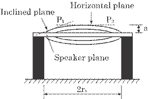
Fig. 5.12 Decomposition
of practical vibration plane into two flat planes; i.e., an
inclined
plane and a horizontal plane.
A. Laser Beam Dispersion
on the Inclined Plane P1
Figure 5.13 shows a
comparison of the laser beam reflections between parallel plates and
non-parallel plates. The laser beam reflected between non-parallel plates
deflects from the one reflected between parallel plate. As was shown in a cut,
when the mirror inclines slightly, ![]() , the reflected light deviates 2
, the reflected light deviates 2![]() from the original direction and this causes a dispersion of
the laser beam. The mean inclination, <
from the original direction and this causes a dispersion of
the laser beam. The mean inclination, <![]() >, can be approximated by
>, can be approximated by
|
|
(5.5) |
where
a is vibration amplitude at the central region and rs is a radius of
the speaker. The light deviates, finally, 2n<![]() > after n times multi-reflection at a vibrating plane, as
shown in Fig. 5.13(b). The dimension of the dispersion on the screen due to the
vibration, W, will, then, be as follows at a distance R from the vibration
plane to the screen.
> after n times multi-reflection at a vibrating plane, as
shown in Fig. 5.13(b). The dimension of the dispersion on the screen due to the
vibration, W, will, then, be as follows at a distance R from the vibration
plane to the screen.
|
|
(5.6) |
Thus,
the multiple reflection used in this method acts as an amplifier of the beam
dispersion caused by the vibration amplitude. The amplification, i.e., the
efficacy of multiple reflection, which is defined by W/W0, can be
given by
|
|
(5.7) |
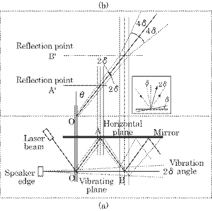
Fig. 5.13 Multiple reflections between parallel
mirrors and non-parallel mirrors. (a)
Practical multiple reflections, and (b) laser beam profile symmetrical
to a plane
mirror.
where
W0 is the beam spread represented by a single reflection, n=1. For
example, we can obtain W = 2mm for a practical dimension of a = 10![]() m, rs = 5 mm, R = 100 mm, and n = 5. This value of
W = 2mm can easily be observed by the naked eye. The actual inclination will be
larger than the mean value given by Eq. (5.5) since the central zone of the
speaker plane becomes horizontal. Thus, the actual spread dimension will be
larger than W. This causes an error and will be discussed in section 5.3.3.
m, rs = 5 mm, R = 100 mm, and n = 5. This value of
W = 2mm can easily be observed by the naked eye. The actual inclination will be
larger than the mean value given by Eq. (5.5) since the central zone of the
speaker plane becomes horizontal. Thus, the actual spread dimension will be
larger than W. This causes an error and will be discussed in section 5.3.3.
B. Laser Beam Dispersion
on the Horizontal Plane P2
In this case, in
contrast to the case of the inclined plane, the laser beam does not diverge in
itself in a free space since the direction of the laser beam does not deviate
from that on the stationary plane. This renders the amplitude measurement
difficult. However, application of multiple reflection can overcome this
difficulty.
Figure 5.14 shows an
illustration of the multiple reflection between the horizontally vibrating
plane and the plane mirror. The reflection on the horizontally vibrating plane
does not deflect the direction of the laser beam, but it rather increase the
spread as shown in Figure 5.14(a). The spread of the laser beam at the
vibrating plane, W', can be expressed as
|
|
(5.8) |
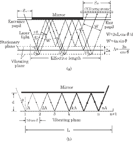
Fig. 5.14 Multiple reflections between a
horizontally vibrating plane and a stationary mirror. (a) Illustration of the beam
spread. (b) Aspect of multiple reflections.
Thus,
no spread exceeds 4a. The spread after a multiple reflection, however, can be
larger than 4a. The spread after n times reflections can be calculated from a
simple geometric consideration, as follows:
|
|
(5.9) |
where
L is an effective length of the vibrating plane mirror, ![]() is an incident angle
of the laser beam, and d is a distance between the vibrating plane and the
mirror.
is an incident angle
of the laser beam, and d is a distance between the vibrating plane and the
mirror.
The amplification of the
spread due to multiple reflection defined by W/W' is then
|
|
(5.10) |
High
amplification can, therefore, be obtained by using a large L, a small d, and a
small ![]() . Remarkably small values for d would be impractical. We
choose d = 0.5 mm, L = 2 mm, and
. Remarkably small values for d would be impractical. We
choose d = 0.5 mm, L = 2 mm, and ![]() =
= ![]() /18, for a = 10
/18, for a = 10![]() m with a practical speaker dimension of rs = 5 mm.
We then obtained W/W' = 11.34, and W = 78.8
m with a practical speaker dimension of rs = 5 mm.
We then obtained W/W' = 11.34, and W = 78.8![]() m, which may be measured easily by CCD camera.
m, which may be measured easily by CCD camera.
Practical beam spread is
a superposition of both the spreads expressed by Eqs. (5.6) and (5.9),
|
|
(5.11) |
As
discussed above, the dispersion on the inclined plane is rather large as
compared with that on the horizontal plane for the speaker used in this study
(dimension of rs = 5 mm and mean vibration amplitude of a = 10![]() m).
m).
5.3.3 Experimental
Results and Discussions
A preliminary experiment
was conducted by using a large-scaled optical arrangement and by replacing the
vibration amplitude with the static displacement of the mirror. That is, the
displacement was considerably enlarged as compared with the practical
dimensions for a convenience of measurement.
Figure 5.15 shows an
example of a laser beam deflection on the inclined plane mirror. The
divergence
of the laser beam increased linearly in accordance with the multiple reflection
as predicted in section 5.3.2. Table 5.3 shows a laser beam spread on the
horizontal plane mirror for some values of d and ![]() . The spread, W/W', also agreed well with the calculated
values given by Eq. (5.10). From these results, the proposed method in this
paper was found to be valid.
. The spread, W/W', also agreed well with the calculated
values given by Eq. (5.10). From these results, the proposed method in this
paper was found to be valid.
In this preliminary
experiment, the laser beam from a He-Ne laser was used directly, but a laser
beam with a small cross-section would be desirable in a practical use since a
speaker plane is very small. This can be done easily by using the mirror with a
small entrance pupil as shown in Figure 5.14(a). However, too small a pupil
would cause a diffraction effect, which makes a detection of the beam spread
difficult, and a proper beam size will be 500~1000 ![]() m.
m.
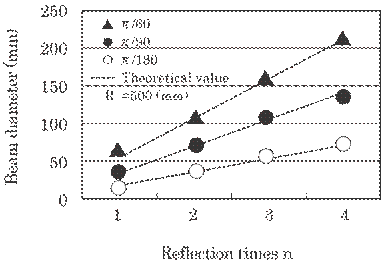
Fig. 5.15 The laser beam
deflection on the inclined plane mirror.
Table 5.3 The laser beam
spread on the horizontal plane mirror under the experimental
condition of a = 1 mm and L = 100 mm.
|
|
d(mm) |
W'(mm) |
W(mm) |
W/W'(mm) |
|||
|
|
10 |
|
2.8 |
|
14.1 |
|
5.0 |
|
|
|
Exp. |
2.9 |
Exp. |
14.1 |
Exp. |
4.9 |
|
|
20 |
|
2.8 |
|
7.0 |
|
2.5 |
|
|
|
Exp. |
2.8 |
Exp. |
7.2 |
Exp. |
2.6 |
|
|
|
|
|
|
|
|
|
|
|
10 |
|
3.5 |
|
10.0 |
|
2.9 |
|
|
|
Exp. |
3.5 |
Exp. |
9.8 |
Exp. |
2.8 |
|
|
20 |
|
3.5 |
|
5.0 |
|
1.4 |
|
|
|
Exp. |
3.5 |
Exp. |
4.9 |
Exp. |
1.4 |
Figure 5.16 shows an
illustrative intensity profile of the laser beam on the observation plane. The
broken curve represents the cross-sectional intensity of the laser beam itself,
which is obtained by multiple reflection on a stationary mirror, and the solid
curve represents the intensity profile obtained by multiple reflection on a
vibrating plane. The intensity will, thus, fade around the edge region, Wp,
due to the vibration, as discussed in sections 5.3.2. The value can be detected
by using a CCD array sensor and a microscopic observation.
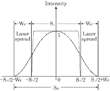
Fig. 5.16 An illustration of a light intensity
profile on an observation plane. Broken curve represents the intensity
reflected on the stationary plane, and the solid curve represents that on the
vibrating plane.
In this preliminary
experiment, the beam spread due to both inclined planes and parallel planes was
detected separately. However, these spread are incorporated and cannot be
detected separately in practice, as shown in Eq. (5.11). This causes a
measuring error of this method. The considerable error factors of this method
will result from a diffraction effect due to too small an entrance pupil, a
laser beam divergence and a detection error. The first and the second factors
will be eliminated since only a beam spread, Wp, due to vibration
can be detected separately. Therefore, the remaining error factors will be the
detection errors arising from a resolution of the detector and an
indistinctness of the causes of the beam spread. The later error cannot be
discussed theoretically; it can, only, be discussed experimentally. Only the
former error factor will, then, be discussed in this paper. We can obtain the
measuring errors for the vibration amplitude, ![]() a, from Eqs. (5.6) and (5.9), as follows:
a, from Eqs. (5.6) and (5.9), as follows:
|
|
(5.12) |
Where
![]() W is a resolution of the detector. The measuring error on the
inclined plane mirror is, then,
W is a resolution of the detector. The measuring error on the
inclined plane mirror is, then, ![]() a=(1/200)
a=(1/200)![]()
![]() W for the previous values of rs=5 mm, n=5 and
R=100 mm, and that on the parallel mirror is
W for the previous values of rs=5 mm, n=5 and
R=100 mm, and that on the parallel mirror is ![]() a=(0.127)
a=(0.127)![]()
![]() W for the previous values of d=0.5 mm, L=2 mm and
W for the previous values of d=0.5 mm, L=2 mm and ![]() =
=![]() /18. The resolution of the CCD camera is usually a few
microns and then the measuring error due to a resolution of the detector can be
sub-microns.
/18. The resolution of the CCD camera is usually a few
microns and then the measuring error due to a resolution of the detector can be
sub-microns.
In conclusions, the
following results were obtained.
(1)
This method uses multiple reflection between a vibrating plane and a plane
mirror parallel to that vibrating plane, which is very simple.
(2)
The measuring sensitivity of this method ranges between sub-microns and 1mm,
which is sufficiently high for practical use.
5.4 Torsion Sensor in
Power Transmission Shaft
5.4.1 Introduction
Metal shafts have long
been used for the transmission of mechanical power. Examples include screw
shafts and crank shafts in cars. Torsion is normally generated by a load since
shafts are usually a few meters in length and a few cm in diameter.9)
Over time, shafts tend to break suddenly due to metal fatigue and overload.
Such breakdowns will occasionally cause disastrous accidents. It is therefore
desirable to monitor torsion in a rotating shaft in realtime.
In this section, we
propose and verify a practical system to monitor torsion. The present method is
based on laser reflection.
5.4.2 Principle and
Method
We have previously
proposed an optical method for detecting torsion in a power transmission shaft.10)
The basic principle of the present method is based on light reflection. Figure
5.17 shows the sensor head of the system. Two pairs of light sensors are used
for this
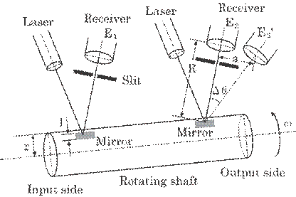
Fig. 5.17 Proposed
sensor head for detecting torsion in a shaft.
purpose.
One is attached to the input side of the shaft and the other to the output
side. A load will cause torsion to occur between them. A pair of light sensors
consists of a light source, mirror, slit, and light receiver. The light
reflected on the mirror is captured by the receiver. A semiconductor laser is
used as a light source and a silicon photodiode is used as a light receiver.
The slit attached in front of the silicon photodiode is used to shield ambient
light and obtain a square-like light signal. A curved mirror with the same
curvature as the shaft is used, thus, both pulse signals are obtained
simultaneously by the receivers when the laser illuminates the rotating
mirrors. No time difference will exist between both signals when both mirrors
are attached to the shaft in the same axial direction. A time difference ![]() t will, however, be produced due to torsion. The torsion
angle
t will, however, be produced due to torsion. The torsion
angle ![]() is in direct
proportion to the time difference
is in direct
proportion to the time difference ![]() t as follows:
t as follows:
|
|
(5.13) |
where
![]() is the rotational
frequency of the shaft. Thus,
is the rotational
frequency of the shaft. Thus, ![]() can be detected by
measuring
can be detected by
measuring ![]() t.
t.
Figure 5.18 shows the
principle of this method and Fig. 5.19 presents the system. Initially,
Fig.5.18 Method for
measuring the torsion in realtime.
both
received signals are transformed to square waves by a comparator. The time
difference between them , ![]() t, can then be measured by a logic circuit and is finally
digitized by an oscillator and a counter. The frequency of the oscillator, f
Hz, determines the time resolution, i.e., measurable smallest amount of time
t, can then be measured by a logic circuit and is finally
digitized by an oscillator and a counter. The frequency of the oscillator, f
Hz, determines the time resolution, i.e., measurable smallest amount of time ![]() t(=1/f). That is, the time difference is measured
t(=1/f). That is, the time difference is measured
by
a relation, ![]() t = n
t = n![]()
![]() t, where n is a pulse number within the time difference. The
number
t, where n is a pulse number within the time difference. The
number
n can be detected by the
counter. The torsion angle ![]() can then be given by
can then be given by
|
|
(5.14) |
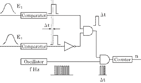
Fig.5.19 System for
measuring the time difference digitally.
In order to measure the
torsion accurately, the pulse number, n, in each time difference, ![]() ti, was averaged over reasonable periods, Ta(=m
ti, was averaged over reasonable periods, Ta(=m![]() 2
2![]() /
/![]() ), as shown in Fig. 5.20. The number m shows an integer that
determines an interval for averaging. Each time difference at the sampling
synchronized to the rotational frequency of the shaft has a different value,
), as shown in Fig. 5.20. The number m shows an integer that
determines an interval for averaging. Each time difference at the sampling
synchronized to the rotational frequency of the shaft has a different value, ![]() ti(i=1~m), mainly due to the vibration of the
shaft and the load. The pulse number thereby has a different value, n(
ti(i=1~m), mainly due to the vibration of the
shaft and the load. The pulse number thereby has a different value, n(![]() ni). In this paper, we denote the averaged values
by < >, e.g., <
ni). In this paper, we denote the averaged values
by < >, e.g., <![]() t>, <n> and <
t>, <n> and <![]() >. The average has an effect on the estimated amount of
torsion. This will be discussed further in section 5.4.4.
>. The average has an effect on the estimated amount of
torsion. This will be discussed further in section 5.4.4.
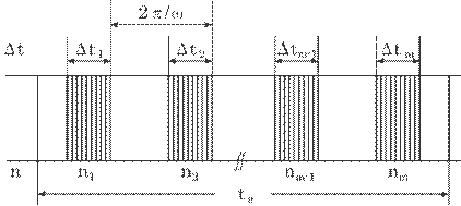
Fig. 5.20 Method for
averaging.
5.4.3 Results
A preliminary experiment
was conducted in order to verify the method. It is difficult to produce torsion
experimentally. Torsion was simulated in the present study by a slight shift of
the light receiver, E2 to E2', as shown in Fig. 5.17. The
distance from the mirror to the receiver was R = 300 mm.
In the present
experiment, there existed a small time difference between both light receivers,
![]() t0, even in the absence of torsion,
t0, even in the absence of torsion, ![]() = 0. This was because of the optical arrangement of the light
sources, the mirrors, and the light receivers. The net time difference,
= 0. This was because of the optical arrangement of the light
sources, the mirrors, and the light receivers. The net time difference, ![]() t, is then
t, is then
|
|
(5.15) |
where
![]() ts represents the time difference, from when the
torsion was simulated. An integer n0 represents the pulse number
within
ts represents the time difference, from when the
torsion was simulated. An integer n0 represents the pulse number
within![]() t0 and ns within
t0 and ns within ![]() ts.
ts.
Table 5.4 presents a few
examples of the pulse number for three different amounts of torsion. 20 samples
were averaged, i.e., m = 20. The error rate of the pulse number from the mean
value was within 5%. The accuracy of the torsion angle may then exceed 95% even
without averaging. In this experiment, the rotational frequency was ![]() = 2
= 2![]()
![]() 10 and the frequency of the oscillator was f = 1 MHz.
10 and the frequency of the oscillator was f = 1 MHz.
The net time difference ![]() t can then be obtained by Eq. (5.15), and the torsion amount
t can then be obtained by Eq. (5.15), and the torsion amount ![]() by Eq. (5.14). The
shift amount of the light receiver, a, can easily be obtained by a relation
<a>= R
by Eq. (5.14). The
shift amount of the light receiver, a, can easily be obtained by a relation
<a>= R![]() <
<![]() >. Table 5.5 shows these values for three amounts of
shift. It can be seen in table 5.5 that the measured torsion, a, agrees well
with this method's calculated torsion <a>. Thus, the method used in this
study was found to be valid.
>. Table 5.5 shows these values for three amounts of
shift. It can be seen in table 5.5 that the measured torsion, a, agrees well
with this method's calculated torsion <a>. Thus, the method used in this
study was found to be valid.
Table 5.4 Pulse numbers
within each time difference![]() ti(i=1~20) for three different amounts of
simulated torsion.
ti(i=1~20) for three different amounts of
simulated torsion.
|
no |
Error
rate (%) |
ns-no |
ns'-no |
ns''-no |
|
72 |
7.46 |
59 |
86 |
124 |
|
71 |
5.97 |
57 |
88 |
122 |
|
66 |
-1.49 |
64 |
90 |
128 |
|
70 |
4.48 |
59 |
89 |
122 |
|
63 |
-5.96 |
65 |
95 |
128 |
|
67 |
0.00 |
63 |
93 |
126 |
|
71 |
5.97 |
58 |
87 |
122 |
|
63 |
-5.97 |
66 |
94 |
128 |
|
68 |
1.49 |
62 |
93 |
125 |
|
70 |
4.48 |
58 |
89 |
124 |
|
63 |
-5.97 |
64 |
96 |
128 |
|
68 |
1.49 |
62 |
94 |
124 |
|
68 |
1.49 |
60 |
91 |
126 |
|
65 |
-2.99 |
66 |
98 |
126 |
|
69 |
2.99 |
61 |
90 |
123 |
|
65 |
-2.99 |
63 |
93 |
133 |
|
66 |
-1.49 |
62 |
94 |
125 |
|
70 |
4.48 |
59 |
89 |
122 |
|
64 |
-4.48 |
66 |
92 |
129 |
|
66 |
-1.49 |
65 |
94 |
124 |
|
Ave=67 |
|
Ave=62 |
Ave=92 |
Ave=126 |
Table 5.5 Calculated and
measured torsions with pulse number and time difference.
Experimental conditions: frequency of
the oscillator, f = 1 MHz; rotational
frequency of the shaft, ![]() = 2
= 2![]()
![]() 10; distance from mirror to receiver, R = 300 mm.
10; distance from mirror to receiver, R = 300 mm.
|
|
Torsion |
||
|
|
|
|
|
|
Pulse
number <ns-no> |
62 |
92 |
126 |
|
Time
difference < |
62 |
92 |
126 |
|
Calculated
torsion angle < |
3.89 |
5.78 |
7.91 |
|
Calculated
amount of shift <a> (mm) |
1.17 |
1.73 |
2.37 |
|
Measured
amount of shift a (mm) |
1.0 |
1.8 |
2.4 |
5.4.4 Discussions
A. Accuracy
The error of the torsion
depends on a fluctuation of n, f, and ![]() , as shown in Eq. (5.14). The values of n and
, as shown in Eq. (5.14). The values of n and ![]() will continually
fluctuate due to the load and the vibration of the shaft. The rotational frequency
will continually
fluctuate due to the load and the vibration of the shaft. The rotational frequency
![]() will continually
fluctuate due to a load. The fluctuation, however, has no effect on accuracy
because both mirrors are attached to the same shaft. In addition, the high
frequency oscillator does not fluctuate. Therefore, the only remaining possible
error factor would be the fluctuation of n caused by a vibration of the shaft,
will continually
fluctuate due to a load. The fluctuation, however, has no effect on accuracy
because both mirrors are attached to the same shaft. In addition, the high
frequency oscillator does not fluctuate. Therefore, the only remaining possible
error factor would be the fluctuation of n caused by a vibration of the shaft, ![]() n. The fluctuation i.e., error rate of the pulse number from
the mean value, was a few percentages, which determines the accuracy of this
method.
n. The fluctuation i.e., error rate of the pulse number from
the mean value, was a few percentages, which determines the accuracy of this
method.
It is, however, possible
to reduce the error to a negligibly small amount by averaging the measured
values of n over a period of them, Ta(=m![]() 2
2![]() /
/![]() ), as described in section 5.4.2, because the sum of
), as described in section 5.4.2, because the sum of ![]() ni becomes zero. The data for the torsion can then
be obtained at an interval of Ta. The interval Ta will
usually be smaller than 1 s in practical use. The data can then be obtained in
realtime. Thus, the method described in this paper will be free of error
factors in principle.
ni becomes zero. The data for the torsion can then
be obtained at an interval of Ta. The interval Ta will
usually be smaller than 1 s in practical use. The data can then be obtained in
realtime. Thus, the method described in this paper will be free of error
factors in principle.
B. Resolution of the
Torsion Angle
The resolution of the
torsion angle, i.e., detectable minimum torsion angle, is determined by ![]() /f, as expressed in Eq. (5.14). High resolution can thus be
obtained with the high frequency of the oscillator. In this preliminary
experiment, the resolution of the torsion angle,
/f, as expressed in Eq. (5.14). High resolution can thus be
obtained with the high frequency of the oscillator. In this preliminary
experiment, the resolution of the torsion angle, ![]() min, can be calculated as
min, can be calculated as ![]() min = 2
min = 2![]()
![]() 10-5 radian for f = 1MHz and
10-5 radian for f = 1MHz and ![]() = 2
= 2![]()
![]() 10. The rotational frequency
10. The rotational frequency ![]() = 2
= 2![]()
![]() 60 is usually used as power transmission. In this case, it
becomes
60 is usually used as power transmission. In this case, it
becomes ![]() min = 1.2
min = 1.2![]()
![]() 10-4, which is more than sufficient for practical
use.
10-4, which is more than sufficient for practical
use.
C. Mirror Size
In order for the logic
circuit to work effectively, the time difference ![]() t should be smaller than the pulse width
t should be smaller than the pulse width ![]() tp of the received signal, as shown in Fig.
5.18(a). This determines the mirror size l of the
tp of the received signal, as shown in Fig.
5.18(a). This determines the mirror size l of the ![]() direction, l = r
direction, l = r![]()
![]() r, where r is a radius of the shaft (see Fig.
5.17). That is, the size
r, where r is a radius of the shaft (see Fig.
5.17). That is, the size ![]() , should be larger than anticipated maximum
torsion angle
, should be larger than anticipated maximum
torsion angle ![]() ,
, ![]() m. The value of
m. The value of ![]() m = 1
m = 1![]() 10-2 rad. will be more than sufficient for
practical use. The minimum mirror size is therefore l = 0.4 mm for r = 40 mm.
Furthermore, in practice, the pulse width
10-2 rad. will be more than sufficient for
practical use. The minimum mirror size is therefore l = 0.4 mm for r = 40 mm.
Furthermore, in practice, the pulse width ![]() tp will be elongated by the laser beam size at the
receiver.
tp will be elongated by the laser beam size at the
receiver.
In
conclusions, the following results were obtained.
(1)
The system is highly accurate, i.e., exceeds 95% accuracy.
(2)
The system shows very high resolution for the torsion angle, that is, the
smallest measurable torsion angle is 1.2![]()
![]() 10-4 rad for a rotational frequency of 2
10-4 rad for a rotational frequency of 2![]()
![]() 60 and an oscillator frequency of 1 MHz, which is more than
sufficient for practical use.
60 and an oscillator frequency of 1 MHz, which is more than
sufficient for practical use.
(3)
The system is relatively simple.
(4)
The system can effectively be used for monitoring small changes in torsion in
realtime.
References
1) M. Ueda, S. Mizuno, & A. Matsumura:
Realtime optical sensor for dye color and concentration detection. Rev. Laser
Eng., 22-10(1994) p. 828. Ref. No. 7) in Chap. 4
2) M. Ueda, S. Mizuno, A. Matsumura, & F.
Sakan: Real-Time Optical Monitoring System for Dye Colour and Concentration.
Opt. Lasers Eng, 25(1996) p. 13.
3) M. R. Osborne, Nonlinear least squares-The
Levenberg algorithm revisited. J. Australian Mathematical Society., 19 (1976)
p. 343.
4) M.Ueda, M.Kawazu and H.Suga: A laser system
for cloth filaments, Opt. Laser Eng. 28(1997) p.71.
5) M.Kawazu, M.Ueda and H.Suga: A practical
system for counting cloth filaments by sheet like laser beam, Rep. Top. Meet.
Laser Soc. No. RTM-97-3 (1997) p. 13.
6) J. P. Den Hartog, Mechanical Vibrations, 4th
Eds., McGraw Hill (1956).; O. Taniguchi & S. Fujii, Trans. (1998),
7) R. J. Collier, C. B. Burckhardt, & H. L.
Lawrence : Optical holography, Academic Press (1971) p. 438.
8)
Eds.
K. Takahashi, etc., Handbook for the Sensors, Asakura (1991) p. 324.
9) JSME ed.: Mechanical Engineers' Handbook,
Jpn. Soc. Mech. Engrs. (1987) A4-43.
10) M. Ueda, T. Yamaguchi, J. Chen, K. Asada, K.
Taniguchi, and H. Suga, "An optical method for detecting torsion in a
power transmission shaft in realtime", Rev. Laser Engr., 26-11(1998) p.
821.
11) M. Ueda, T. Yamaguchi, J. Chen, K. Asada, K.
Taniguchi, and H. Suga, "An optical system for monitoring torsion in a
power transmission shaft in realtime", Opt. Laser Engr., 31-3(1999) p.
199.
[Chapter 5
Part II will be presented in the upcoming September-October 2010 issue of this Journal.]
[ BWW Society Home Page ]
© 2009-2010 The Bibliotheque: World Wide Society