Fundamentals and Practices of Sensing Technologies
by Dr.
Keiji Taniguchi, Hon. Professor of
Xi’ an
Dr. Masahiro Ueda, Professor of Faculty of Education and Regional Studies
Dr. Ningfeng Zeng, an Engineer of Sysmex Corporation
(A Global Medical Instrument
Corporation),
Dr. Kazuhiko Ishikawa, Assistant Professor
Faculty of Education and
Regional Studies,
Preface
The sensing technologies have been dramatically improved in the following two points:
(1) Constructing more reliable systems based on integration between sensing devices (or transducers) and signal processing function which are produced by using integrated circuit technologies,
(2) Constructing systems that can utilize the information more effectively and can control the object more easily. For example, in power plants, the systems are connected among other sensing systems by means of the networks. On a battlefield, remote surgery system which vision-sensors and robots are used is an outstanding example (see Fig.1.18).
This is a textbook for learning basic principles and its applications of the sensing systems and for leaning the practical sensing systems required for constructing these systems. As described above, the sensing technologies contain a wide variety of system technologies. This book, however, is described to be in focus for the sensing system using a personal computer.
In Chapter 1, the representative sensing systems, i.e., sensing devices or transducers, relating circuits, and several systems using these elements and circuits are described.
In Chapter 2, several classical sensors, which are used in contact with a measuring point, are described.
In Chapter 3,
several of recent ceramic sensors are presented. Those were developed, studied
by many researchers, and were produced by sophisticated techniques of a
corporation in
In Chapter 4, some practical sensing technologies, which basically use transmitted and attenuated lights, are described.
In Chapter 5, some practical sensing technologies, which basically use scattered and reflected lights, are described.
In Chapter 6, some practical sensing technologies, which basically use electric and electromagnetic fields, are described.
In Chapter 7, some of practical sensing technologies, which have been commercially used in medical and healthcare measurements, are described.
These practical sensing technologies described from Chapters 4 to 6 were all attained as the results of our joint research works with several companies, and some of them have been used in the practical plants. These technologies are basic in principle and simple for construction, and then can be applied in other purposes. The technologies for the measurements of the surface displacement described in sections 5.8 and 5.9 in Chapter 5, in particular, uses the merits of laser light, which result in high resolution, high speed and non-destructive measurements. The ideas in applying basic principles for practical cases are mainly described in this book.
Although the sensing technologies have been secondary situation in many manufacturing plants and never been primary one, however, they play very important roles in these plants and are essential to the development of science and engineering. Furthermore, these technologies enable to high quality products, enable to reduce the labor of factory workers and to deal with emergency in manufacturing plants. In particular, we can save waste of resources by applying the sensing technologies and conserve the environments. Thus, the sensing technologies are the most important ones for scientific and practical situations.
The contents in Chapters 1~3, are a basis for sensors and electronic measurements. Therefore, they are intended for the undergraduate students in the university. Furthermore, the GPS and RFID Tags described in Sections 1.5 and 1.6 in Chapter 1 of this book, are additionally attached to that of the Japanese version of our book, entitled “Practical Sensing Technologies”.
The
contents in Chapters 4~6, are ‘practical applications of this basis to the
manufacturing plant’ and thus, they are intended for engineers in the
industries and also for graduate students and university men, because they have
been lectured as subjects for general education in
This book was written in the responsibility of the chapters as shown in the following table:
|
Keiji Taniguchi |
Chapters 1-3, Section 6.3 in chapter 6 |
|
Masahiro Ueda |
Chapters 4 - 6 |
|
Zeng Ning Feng |
Chapter 7 |
|
Kazuhiko Ishikawa |
Chapter 4 |
Acknowledgements
We express our heartfelt thanks to the authors of many books, papers and data which have been used as references in this book. Especially, we express our heartfelt thanks to Mr. Osamu Murata, one of the establishers of Murata Co. Ltd. and everybody in ones.
Lastly, we thank to the President and Director: Mr. John Pellam, Bibliotheque: World Wide International Publishers.
Keiji Taniguchi, Masahiro Ueda, Zeng Ning Feng
and Kazuhiko Ishikawa
Chapter 1: Overview for Sensors and Electronic Measurements
Summary
In this chapter, we provide an overview of several transducers and sensors, and
some of the assemblies and systems using them, as an introduction. In section
1.1, the relationships between sensors or transducers and the measurement systems,
in section 1.2, transduction principles for traditional physical sensors, in section 1.3, outlines of radar sensors, in section1.4, outlines of GPS system, and in section1.5, outlines of RFID Tags are described.
1.1 Relationships between Sensing Elements and Measurement Systems
1.1.1 Block Diagram of Measurement System
Figure 1.1 shows an example of a process diagram for monitoring the operational condition in a plant system.
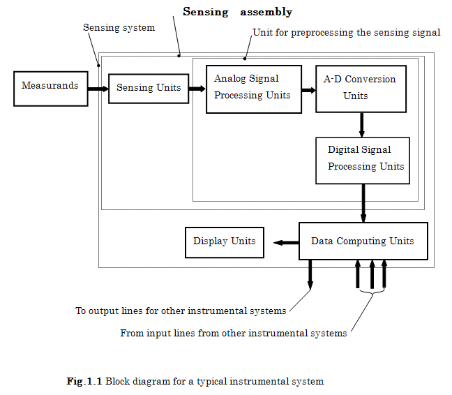
This system consists of sensing units, analog signal processing units, A-D conversion units, digital signal processing units, data computing units, and display units.
Details in this block diagram will be explained in the next section.
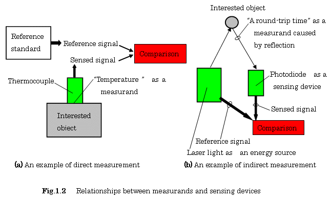
1.1.2 Methods for Obtaining Measurands from Interested Object (1)
Let’s consider here the following two methods for sensing a measurand, which is
a physical quantity, property, or condition:
(1) Direct measurements based on calibration of the reference standard. Examples would be a position or a displacement, a time, a velocity, an acceleration, a force or a pressure, a temperature, etc.
(2) Indirect measurements based on radiations of wave energy such as acoustic waves, laser beams and radio waves.
Figure 1.2 shows an illustration of the two methods, i.e., direct and indirect
measurements.
1.1.3 Transducers and Sensors (1)
In a sensing unit, there are two types of unit, transducer and sensor. Transducer and sensor are the devices that can obtain a usable electrical signal of a specified measurand from an interested object. Figure 1.3 shows the structures of transducers and sensors, respectively.
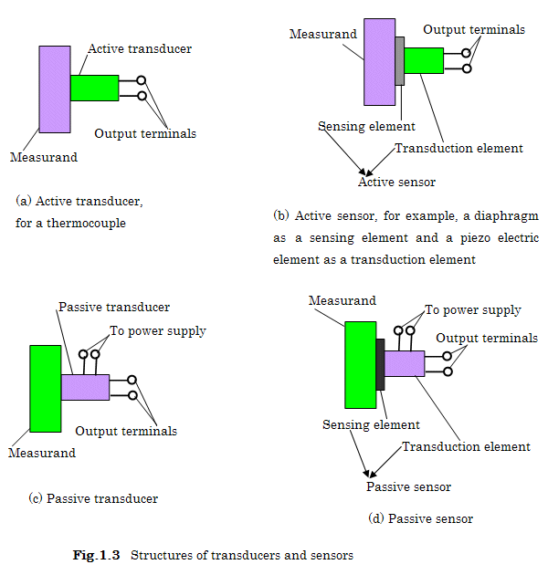
A thermocouple by itself, which is a self-generating element, can sense an electrical signal and transform it into a calibrated electrical signal as shown in Fig. 1.3(a). On the contrary, a piezoelectric sensor for the pressure measurement has two separable coupling elements for sensing and transduction, as shown in Fig. 1.3(b). These types of transducers are active devices operating without any excitations from an external power supply. However, most transducers or sensors are passive devices that require excitations from an external power supply, as shown in Figs. 1.3 (c) and 1.3 (d).
We will discuss here several kinds of transducers and sensors.
A. Physical Transducers or Sensors
Physical transducers or sensors are used for measuring physical quantities such as a force, a displacement, a velocity, an acceleration, a temperature, an electrical resistance, and so on.
Physical transducers and sensors are used in almost all the examples throughout this book.
【Example 1.1】
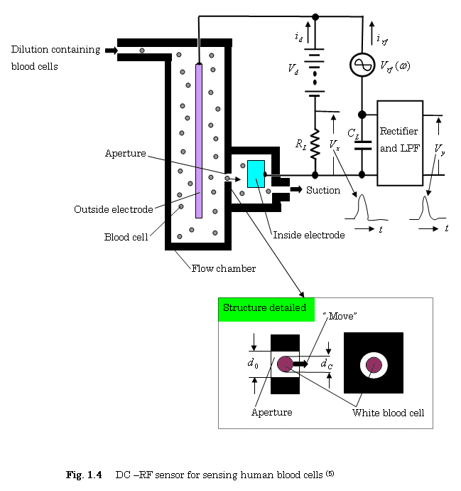
Our first example is the sensing technology for human blood cells passing through an aperture in a flow chamber. Figure1.4 shows a DC-RF(Direct Current and Radio Frequency)sensing method for classifying human blood cells into several categories(2),(3),(4),(5),(6),(7),(8) .
(A) Operation of DC-RF Sensor
As
shown in Fig. 1.4, blood cells suspended in dilute water pass through the
aperture in the flow chamber by the suction pump of the sheath- flowing system
(See Fig. 1.28).
The
cross-sectional area in the aperture, where the DC and the RF currents flow
between the inside electrode and the outside one, is slightly decreased by a
blood cell and the resistance and the impedance between them are increased
slightly due to this action. The output signals ![]() and
and ![]() can, then, be obtained as pulse-shaped waveforms.
can, then, be obtained as pulse-shaped waveforms.
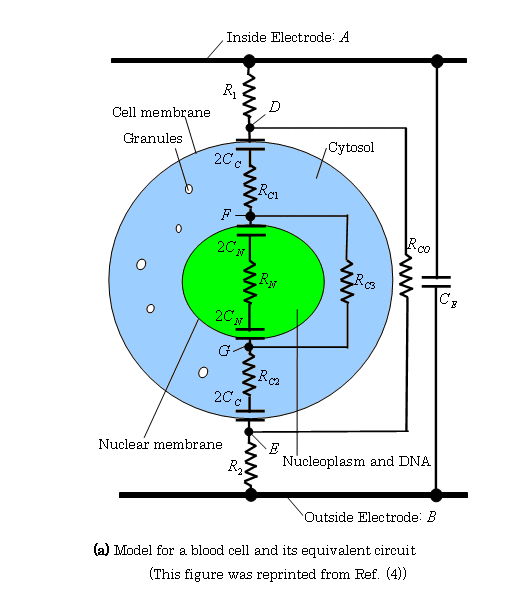
(B) Electrical Model for Blood Cells (4)
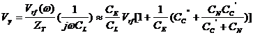
Figure 1.5(a) shows the model for a blood cell and its equivalent circuit. The equations related to the impedance can then be obtained as follows:
(i) Impedance between F and G:
![]() , where
, where ![]()
(ii) Impedance between D and E:
![]() , where
, where ![]() ,
,![]() is a resistance of
the blood cell.
is a resistance of
the blood cell.
As shown in Fig. 1.5(b), a more simplified model can be obtained from the electrical model shown in Fig. 1.5(a).
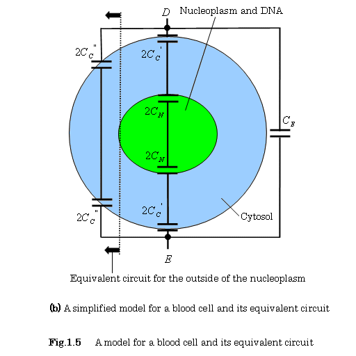
If ![]() ,
, ![]() , then
, then
(C) Estimation of Output Signals obtained by DC-RF Sensor
Using
the practical approximation described above, the output signals ![]() and
and ![]() can be expressed by
the following equations:
can be expressed by
the following equations:
![]() ,
, ![]() (1)
(1)
 (2)
(2)
where, 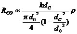 ,
,  ,
,
|
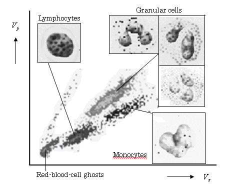
Figure 1.6 shows an example of the two-dimensional scattergram obtained by the RF-DC sensor shown in Fig. 1.4.
The figure shows that the sensor can differentiate the normal white blood cells(WBC) into three categories of lymphocytes, monocytes, and granular cells.
(D) Sensing Techniques for Eosinophils and Basophils
The groups of eosinophils and basophils nuclei whose cytoplasms were melted by chemical processing, flow through their separate measurement channels, as shown in Fig.1.7. They can then be detected by using the DC sensing circuit shown in Fig.1.4.
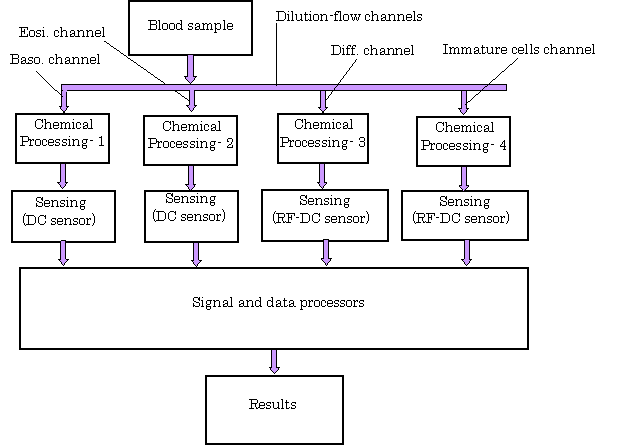
Fig. 1.7 Flow diagram
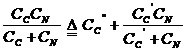
for WBC differentiation (5), (6)
The histograms shown in Figs.1.8 (a) and (b) were obtained by sensing white blood cells and processing their analog signals. Eosinophils and basophils can be measured by the following threshold-operations:
Number of basophils: ![]() (3)
(3)
Number of eosinophils: ![]() (4)
(4)
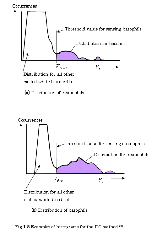
(E) Number of Neutrophiles
Neutrophiles can be calculated by the following formula:
(Number of neutrophiles) =( Number of granular cells) – (Number of eosinophils) – (Number of basophils) (5)
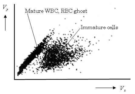
(F) Sensing Immature Cells
Figure1.9 shows an example of the two-dimensional scattergram for sensing immature
Cells. These cells are classified by using a sensor for detecting immature cells shown in
Fig. 1.7.
B. Chemical Sensors(1)
Chemical sensors are used for the measurements of ion concentration in a solution, gas concentration, chemical composition, and the like.
Figure 1.10 shows a sample outline for the measurement of an ion concentration.
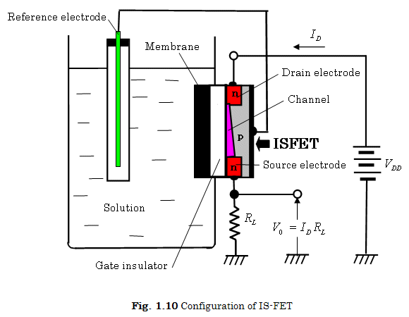
In this figure, IS-FET(Ion Sensitive Field Effect Transistor)can be used for converting
ionic
solutions, such as pH ![]() ,
,![]() ,
, ![]() , etc., into the measurable drain current
, etc., into the measurable drain current![]() . The sensing signal
. The sensing signal ![]() is expressed as a
function of pH by the following equation:
is expressed as a
function of pH by the following equation:
![]()
Examples of Gas Sensors
(1)As an example, oxidizing gases can be sensed by the change in impedance of
![]() ,
,![]() ,etc. (1)
,etc. (1)
(2) As another example, in a gas chromatrographic air analyzer, the change in mass
and thermodynamic properties of gas molecules deposited on the sensed substrate surface can be sensed (1)
C. Bio Sensors (9)
Biosensors have very high selectivity due to biological reactions and binding. Measurands are produced biologically from substances such as antibodies, glucose, enzymes, and the like. Most biosensors require multiple transduction mechanisms to obtain an electrical output signal, as shown in Fig.1.11.
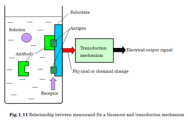
The surface of the substrate shown in Fig.1.11 is coated with an antigen for detecting antibody-antigen binding. When the solution containing antibodies meets the antigen –coated surface of the substrate as a receptor, selective binding occurs between the two. The mechanical properties of the substrate with the bound antibody-antigen complex change slightly as compared with that of an unbound substrate surface. SAW(surface acoustic wave) device is used for sensing this change of the substrate.
This device can, then, produce an electrical signal as a little change in oscillation frequency, when this substrate is used as a device of the feedback loop of an oscillator [(10), pp.1158-1159].
1.1.4 Analog Signal Processing
The sensing signal on the transducer is the analog value with a noise. A low pass filter with amplification is then used to reduce the noise. This processing is generally defined as analog signal processing. Other types of processing such as integration and differentiation are executed after this processing. Details will be described in Chapter 2.
1.1.5 Analog to Digital Conversion(11) , (12)
The signal after the analog processing is then converted into a sequence of digital values by means of an analog to digital (A/D) converter. Figure 1.12 shows the conversion process consisting of three stages, i.e., sampling, quantizing, and encoding.
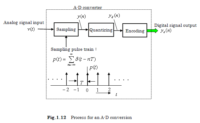
(A)
Sampling Stage:
Analog signal![]() is converted into a sequence of sampled values
is converted into a sequence of sampled values ![]() by means of a periodic
impulse train:
by means of a periodic
impulse train:
![]() ,
where
,
where ![]() is the unit impulse
function and
is the unit impulse
function and ![]() is the sampling
period, respectively.
is the sampling
period, respectively.
The
sampled signal![]() is then expressed by the product of
is then expressed by the product of ![]() and
and ![]() as shown in
Fig.1.14(c),:
as shown in
Fig.1.14(c),:
![]()
![]() ,
,
![]()
![]()
![]()
【Example 1.4】Find a sampled value ![]() when an analog signal
when an analog signal ![]() is sampled by means of
an unit impulse
is sampled by means of
an unit impulse![]() as shown in Fig.1.13(b).
as shown in Fig.1.13(b).
From
Fig.1.13(a), ![]()
Therefore, ![]()
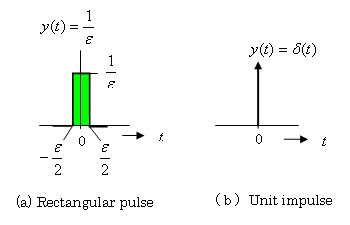
Fig. 1.13 Relationship between a rectangular pulse and a unit impulse
【Example1.5】Find the Fourier transform for a unit impulse train
(1)![]()
(2)From the symmetry property, ![]() ,
,
![]()
【Sampling theorem】
Let
us now consider the Fourier transform![]() of an analog signal
of an analog signal ![]() and the Fourier
transform
and the Fourier
transform ![]() of a periodic impulse
train
of a periodic impulse
train![]() .
.
These
Fourier transforms, ![]() and
and ![]() , can be expressed as follows:
, can be expressed as follows:
![]() ,
, ![]() ,
,![]()
The
graphs of ![]() ,
, ![]() ,
, ![]() , and
, and ![]() are shown in Figs.1.14
(a), (b), (d) and (e), respectively.
are shown in Figs.1.14
(a), (b), (d) and (e), respectively.
The
Fourier transform![]() of
of ![]() can be expressed as
the convolution of the Fourier transforms
can be expressed as
the convolution of the Fourier transforms ![]() and
and ![]() :
:
![]()
where
![]() denotes the operation
of convolution and
denotes the operation
of convolution and ![]() is the sampling
angular frequency.
is the sampling
angular frequency.
Thus,
![]() consists of
periodically repeated copies of
consists of
periodically repeated copies of ![]() , as shown in Fig. 1.14 (f).
, as shown in Fig. 1.14 (f).
These
graphs of ![]() and
and ![]() are also shown in
Figs.1.14 (c) and (f), respectively.
are also shown in
Figs.1.14 (c) and (f), respectively.
It
is evident from ![]() shown in Fig.1.14 (f) that the replica of the angular
frequency spectrum of
shown in Fig.1.14 (f) that the replica of the angular
frequency spectrum of ![]() doesn’t overlap when
the following condition is satisfied in the range of
doesn’t overlap when
the following condition is satisfied in the range of ![]() :
: ![]() or
or ![]()
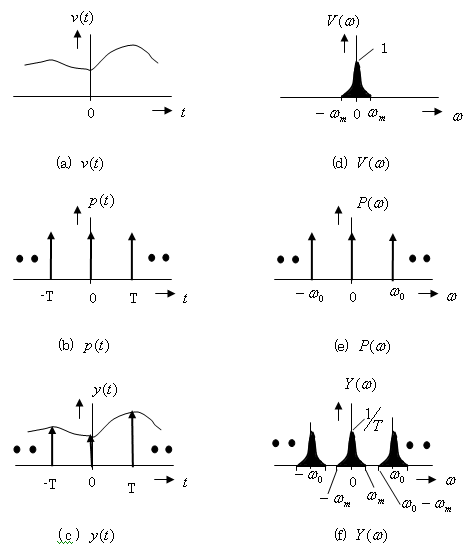
Fig 1.14 Sampling process with a periodic impulse train and with its frequency domain
The
original function ![]() can, then, be recovered from
can, then, be recovered from ![]() by using an ideal low
pass filter, where
by using an ideal low
pass filter, where ![]() (
(![]() ) is the highest angular frequency component as shown in Fig.
1.14(d).
) is the highest angular frequency component as shown in Fig.
1.14(d).
![]() ,
, ![]() (1.1)
(1.1)
(B) Quantizing Stage: Quantizations can be executed at either
uniformly or non-uniformly spaced levels. In the uniformly spaced levels, the
sampled vales ![]() are approximated to the nearest quantization level
are approximated to the nearest quantization level ![]() as shown in the
following formulas:
as shown in the
following formulas:
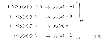
Each
uniformly spaced level is, then, ![]() , when the peak amplitude of the analog signal
, when the peak amplitude of the analog signal ![]() lies in the range of
lies in the range of ![]() and is divided into
and is divided into ![]() intervals.
intervals.
(C) Encoding Stage :
The
quantized samples are encoded into binary symbols. The relationship between ![]() and the number of bits
B for binary symbols is expressed as follows:
and the number of bits
B for binary symbols is expressed as follows:
From
![]() ,
,
∴ ![]() (1.3)
(1.3)
Table 1.1 shows an example of encoding into 8 quantization levels. Each level can, be assigned a 3-bit binary symbol. As an example, 2’s complement code is shown in the right-hand column in this table.
Table 1.1 Example of encoding
Quantization levels |
2’s complement codes |
|
3 |
011 |
|
2 |
010 |
|
1 |
001 |
|
0 |
000 |
|
-1 |
111 |
|
-2 |
110 |
|
-3 |
101 |
|
-4 |
100 |
【Example 1.6】 Find the time interval![]() and the number of bits
and the number of bits![]() , when an analog signal is
, when an analog signal is ![]() ,(
,(![]() :time(sec))and a quantization
interval is
:time(sec))and a quantization
interval is ![]() .
.
![]() ,
, ![]() (bits)
(bits)
![]() (sec)
(sec)
1.1.6 Digital Signal Processing
The digital data after the A/D conversion are processed by means of microprocessors, including digital signal processors (DSP). One example of a conventional DSP process is the linearization of a signal obtained from a non-linear transducer or sensor. Another example of the use of a DSP is as a digital filter required for repetitive mathematical operations of a large number of multiplications and summations such as a FFT (fast Fourier transformation) and an IFFT (inverse FET).
1.1.7 Data Processing
Data processing computers are used for complicated computations such as pattern recognition and computer vision.
References
(1)D. Christiansen : Electronics Engineers’ Handbook, 4th Edition, pp.13.1-13.50
IEEE Press (1997)
(2) K. Taniguchi, H. Ozaki: A New Detecting Circuit for Microcell Counters, Electronics and Communications in Japan,Vol.53-C,No.6, pp.386-392(1970)
(3)
K. Taniguchi, H. Ozaki: Automatic
Microcell Analyzer, Electronics and Communications in
(4)K.H.Schoenbach, R.Nuccitelli, S.J.Beebe: ZAP, IEEE Spectrum,pp.20-24 (August, 2006)
(5)K. Fujimoto:Princioles of Measurement in Hematology Analyzers manufactured by Sysmex Corporation,pp43-60,Sysmex Journal,Vol.22,No1,(Spring, 1999)
(6)Overview of Automated Hematology analyzer XE-2100TM,Product Development
Division, Sysmex Corporation. pp76-84,Sysmex Journal,Vol.22,No1,(Spring, 1999)
(7)H. Ozaki, K.Taniguchi : Sensors and Signal Processing(2nd Edition),p.34, Kyoritsu Pub. Co. Ltd. (1988), (In Japanese)
(8)K. Taniguchi, H. wakamatsu : Medical Electronics and Biomedical Information, pp.140-141,Kyoritsu Pub. Co. Ltd. (1996), (In Japanese)
(9)Y. Horiike, Y.Miyahara: Bio-chips and Bio-sensors, pp.83-84, Kyoritsu Pub. Co. Ltd. (2006), (In Japanese)
(10)R. C. Dorf : Electrical Engineering Hand Book, pp.1158-1159,CRC Press (1993)
(11) B.P.Lathi: Modern Digital and Analog Communication Systems -third edition, pp.81-98,
(12) A.V. Oppenheim and R. W. Schafer: Discrete-Time Signal Processing, pp.114-115, Prentice Hall (1989)
[ BWW Society Home Page ]
© 2009 The Bibliotheque: World Wide Society