|
Abstract
The overall asymmetry (focusing) parameters and energy resolutions of the circulated exiting beam are experimentally investigated using synchrotron X-ray radiation in order to study the characteristic parameters of two Four-block Cyclic germanium Monolithic Monochromators. Correspondence with the theoretical calculated and experimentally registered data are given.
Introduction
Multireflecting closed loop X-ray optical systems, where the wave vector is rotated cyclically with an exiting beam at a definite wavelength are called X-ray resonators (XR). In some theoretically proposed monolithic (with a cavity inside) and polylithic schemes one and the same mirror of the XR is used for the beam “in” and “out” coupling. This can be in principle achieved by using Laue- and Bragg-case reflections through the thinned area of one of the XR’s mirrors [1-7]. Because of technical difficulties, connected with the beam in/out coupling, mixed Laue- and Bragg-case reflections as well as the tuning of various XR monoliths in the polylithic cases, actually none of the proposed XRs was realized until today.
In [8-11] a four-block, germanium, monolithic, spatially focusing X-ray device was constructed and tested (Table-2; l0=lCoKa1= 1,788965Å). The problem of the beam “in” and “out” coupling was circumvented with the help of the entrance and exit gaps which were drilled in the opposite blocks. We call such devices in which the beam circulation path is not closed X-ray Cyclic Monochromators (CMC). According to this definition the resonators in [8-11 and 12-14], as well as the other two discussed here are in fact cyclic monochromators, because of destruction of the closed loop and the existence of separate entrance and exit gaps. In these systems a closed loop was not realized in order to make the experimental characterizations feasible.
The CMCs in general have the same reflection parameters of the exiting beam as the analogous resonators with the closed beam loop. The general theory of these X-ray optical multireflecting systems, effects of spatial and angular autofocusing of the circulating beam, characteristic parameters of the exiting beam and some applications in X-ray optics were discussed in [12-14]. In these systems it is possible to obtain successive not closed direct (counterclockwise) or opposite (clockwise) cycles of the beam circulation and also to change in the cavity the beam trace into opposite direction. With the help of asymmetric reflections CMC can be tuned to different wavelengths so as to achieve autofocusing of the circulating beam.
Theoretical and experimental background
Monolithic
four-block X-ray high resolution asymmetric cyclic monochromators were
constructed from dislocation-free germanium crystals. They are aimed to operate
at ![]() and
and
![]() Bragg
reflections. The uniqueness of this crystal in our case with especially these
reflections were in particularly discussed in [5 and 15]. In the first work it
was shown that in a monolithic reflecting object such as a germanium cavity,
reflections
Bragg
reflections. The uniqueness of this crystal in our case with especially these
reflections were in particularly discussed in [5 and 15]. In the first work it
was shown that in a monolithic reflecting object such as a germanium cavity,
reflections ![]() and
and
![]() forming
90° between each other, are one of the few pairs, which satisfy the condition
of q1+q2=p/2 for the Bragg angles at the wavelength lCoKa1=1,789Å available at a
normal X-ray tube. In the second work it was shown that for the unique case of
forming
90° between each other, are one of the few pairs, which satisfy the condition
of q1+q2=p/2 for the Bragg angles at the wavelength lCoKa1=1,789Å available at a
normal X-ray tube. In the second work it was shown that for the unique case of ![]() Bragg
reflections from germanium the considerable range of Bragg diffracted beam in
the asymmetric case is contained within the symmetric Darwin curve and no
mismatch occurs. This shows that mixed asymmetric and symmetric reflections can
be used in one rigid X-ray reflecting system without loss in energy.
Bragg
reflections from germanium the considerable range of Bragg diffracted beam in
the asymmetric case is contained within the symmetric Darwin curve and no
mismatch occurs. This shows that mixed asymmetric and symmetric reflections can
be used in one rigid X-ray reflecting system without loss in energy.
In addition
to these, the results of a more rigorous treatment involving backscattering
shows, that for the discussed versions of germanium XR and CMC calculations of
reflection curves for ![]() and
and
![]() as
being separate two-beam cases are quite near as in four-beam case.
The further treatment of the four-beam case is under development.
as
being separate two-beam cases are quite near as in four-beam case.
The further treatment of the four-beam case is under development.
The specimens for CMC were oriented and sawn from the germanium crystals with a diamond saw then lapped on different abrasive powders. The orientation was measured on an X-ray goniometer. The material between the mirrors was removed and the gaps were drilled by milling machine and abrasive powder. The cavity’s internal asymmetric mirrors and the positions of the gaps were oriented with the help of a comparator equipped with a special ocular. After a final lapping the specimens were etched in CP-4 at room temperature. No dislocation pits were visible after etching.
General view of two different asymmetric versions of CMCa and CMCb [13] with X-ray optical schemes and beam paths are given in Fig.1 and Fig.2. Their operation is based on successive reflections of a specific wave from all the blocks of the cavity with maximum reflection coefficients and by the total rotation of the beam about 360° per cycle. The entrance and exit gaps of the CMC were cut on the opposite blocks to enable the exiting beam to propagate in the original entering beam direction. It is possible to obtain direct or opposite circulated beams i.e. to operate in spatial focusing (angular defocusing) or spatial defocusing (angular focusing) modes.
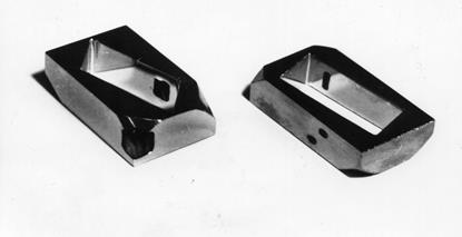
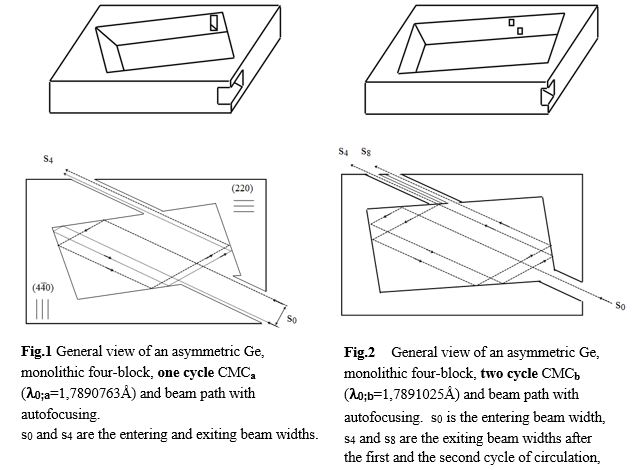
In one of the presented CMC version it is also possible to obtain successive not closed second cycle, too. With a narrow interval of CoKa1 line the CMC can be tested with an X-ray tube, too. Characteristic parameters of these CMC are given in the Table-1.
Table-1
dir. - direct circulation opp. - opposite circulation
|
Parameters |
l0;a dir. opp. |
l0;b dir. opp. |
|
Specific wavelength: l0[Å] |
1,7890763 |
1,7891025 |
|
for (220) for (440) |
16,21° 45,18° |
7,12° 17,07° |
|
of the blocks gn : for (220) for (440) |
3,8 1/3,8 3,0 1/3,0 |
1,7 1/1,7 1,4 1/1,4 |
|
CMC overall asymmetry parameter G: one cycle (w=4) two cycles (w=8) |
0,0077 131 ---- |
0,194 5,2 0,038 26,5 |
|
CMC overall maximum reflection coefficient R(l,q) : one cycle two cycles |
0,621 ---- |
0,740 0,548 |
|
Number of reflections n: in one cycle in two cycles |
4 ---- |
4 8 |
|
Average length of the beam path in CMC[mm]: one cycle two cycles |
41.3 ---- |
41,1 88,2 |
A computer program has been developed for computing reflectivities of XR and CMC with different specific wavelengths as a function of q, the angle of incidence, and l, the wavelength. Some most important parameters describing the exiting from different CMC beams after one direct circulation are presented in the Table-2. Here the terminology and notations are consistent with [12,13]. The 1-st line in this table characterize the asymmetric CMC with l0=lCoKa1= 1,788965Å presented in the Introduction. The 3-rd and 4-th lines characterize the two asymmetric CMCa and CMCb discussed here. The 5-th line characterizes the symmetric version of CMC.
Table-2
dir. - direct circulation opp. - opposite circulation
|
l0 |
Dl1/2 *105 |
l |
Dq1/2[s] |
r [mm] |
G |
Rmax |
||
|
[Å] |
[Å] |
[mm] |
dir. |
opp. |
dir. |
opp. |
|
|
|
1,7889650 |
9,3 |
3,44 |
41,3 |
2,96 |
0,7 |
10,1 |
0,0001 |
0,406 |
|
1,7890275 |
7,7 |
4,16 |
33,6 |
1,63 |
0,9 |
18,3 |
0,0006 |
0,499 |
|
1,7890763 |
6,4 |
5,00 |
24,1 |
0,11 |
1,2 |
274,1 |
0,0077 |
0,621 |
|
1,7891025 |
5,8 |
5,52 |
16,4 |
3,88 |
1,8 |
7,7 |
0,1941 |
0,740 |
|
1,7891056 |
5,5 |
5,82 |
11,2 |
11,2 |
2,7 |
2,7 |
1,0 |
0,763 |
In the Table-2 are presented:
l0 - specific wavelength of the CMC;
Dl1/2 - spectral divergence of the exiting beam at half height of the reflectivity curve;
l - temporal coherence length (l = lo2 / Dl )
Dq1/2 - angular divergence of the exiting beam at half height of the reflectivity curve;
r - spatial coherence length ( r[mm] = 16,7×l[Å]/ Dq[s]);
G - CMC overall asymmetry parameter;
Rmax - CMC overall maximum reflection coefficient.
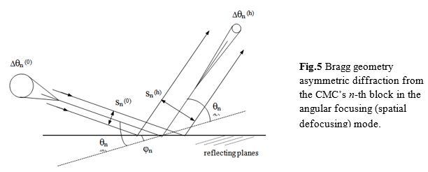
Some of the main parameters of the beam exciting from X-ray multireflecting systems (particularly XR and CMC) can be investigated from the isograms corresponding to half the maximum Rmax1/2 of the bell-shaped Darwin-Prinz reflection surface. The above mentioned two versions of CMCa and CMCb are presented in Fig.3 and Fig.4.
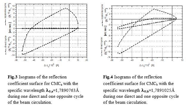
Here the angular divergence of the exiting beam at half height of the reflectivity curve for direct (q4(h)-q4lo(mh)) and opposite (q1(0)-q1lo(m0)) circulation vs. deviation from specific wavelength l0 are plotted. The reflection coefficient isogram for the opposite circulation in Fig.3 is shown by a single line, as at opposite circulation (angular focusing, spatial defocusing) the isograms along the angular axis become much narrower than for the direct circulation. Change of the specific wavelength (different asymmetry parameters) leads to the change of the angular and spectral divergences of the exiting beam (Table-2) for direct and opposite circulations. And for the symmetric case (G=1) the isograms of the opposite and direct circulations are the same.
Theoretically obtained characteristic parameters of the above mentioned CMCa and CMCb were checked experimentally at HASYLAB, beamline E2 (RÖMO1) [16].
Registration of the Spatial Focusing Parameter
Bragg geometry asymmetric diffraction in the real space from the CMC’s n-th block in the angular focusing (spatial defocusing) mode is shown in Fig.5.
The reflecting planes and the entrance crystal surface form an angle j, which is considered positive when the angle between the incidence direction and the crystal surface is smaller than the Bragg angle qB.
An asymmetry parameter gn of the n-th block in w-block CMC is defined by:
(n=1,2,3...w)
![]() (1)
(1)
qn(m0) and qn(mh) are the incident and
reflecting Bragg corrected angels for the selected beam with regards to the n-th
edge asymmetry, corresponding to the maximum reflection; yn(m0) and yn(mh) are the incident and
reflecting angles, with regard to the surface of that block; jn is the plane’s asymmetry
angle. The acceptance angular range is ![]() and
and
![]() ,
where Dqn(s) is the width of Darwin
curve, given for example in [17]. These two equations show that by asymmetric
diffraction it is possible to change the angular divergence of a beam [18,19];
in fact it is
,
where Dqn(s) is the width of Darwin
curve, given for example in [17]. These two equations show that by asymmetric
diffraction it is possible to change the angular divergence of a beam [18,19];
in fact it is ![]() .
Moreover, if sn(0) and sn(h) are the spatial
cross-sections of the incident and diffracted beams, the Liouville’s theorem
requires that sn(0)Dqn(0)= sn(h)Dqn(h) and hence: sn(h) = sn(0)/gn . As a consequence, if gn<1 (angular focusing -
spatial defocusing) the range of total reflection for the emergent beam is gn times smaller than that
of the incident beam, while its spatial cross-section is 1/gn times greater (Fankuchen
effect). In the case of n=1, 2, 3...w reflections in the CMC
we have [20]:
.
Moreover, if sn(0) and sn(h) are the spatial
cross-sections of the incident and diffracted beams, the Liouville’s theorem
requires that sn(0)Dqn(0)= sn(h)Dqn(h) and hence: sn(h) = sn(0)/gn . As a consequence, if gn<1 (angular focusing -
spatial defocusing) the range of total reflection for the emergent beam is gn times smaller than that
of the incident beam, while its spatial cross-section is 1/gn times greater (Fankuchen
effect). In the case of n=1, 2, 3...w reflections in the CMC
we have [20]:
 . (2)
. (2)
Here the overall asymmetry parameter (which is also the focusing parameter) for a multireflecting system as XR or CMC, is determined as [12]:
 . (3)
. (3)
If ½G½< 1, the system operates in condition of spatial focusing and angular defocusing. If ½G½> 1, conversely the system operates in condition of spatial defocusing and angular focusing. If ½G½=1, we have the symmetric case and there is no focusing.
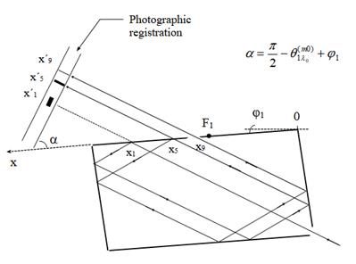
A photographic method was used to determine the overall asymmetry parameter G of CMC by measuring the widths (s) and relative shifts of exiting beams. Agfa dental films were exposed at different distances behind the CMC in order to register the direct (not circulated) and exiting (after 1-st and 2-nd cycles) beams. By detuning the monochromator in front of CMC in the appropriate range of angles the experiment was done with a harmonic free radiation. An X-ray optical schema of the photographic registration is presented on Fig.6. Here xn are the abscissas of the reflections on the same n-th block. For different N cycles we have:
![]() , (4)
, (4)
where n=Nw+n and Fn is the point of focus at that block. x´n are the reflex positions on the film. In the discussed case of CMC, when the exiting block is n=1, for w=4; n=5 (1-st cycle) and n=9 (2-nd cycle) we have:
 (5)
(5)
Thus the values of G were experimentally measured with the help of widths (2) and relative shifts of exiting beams (5).
The theoretical and experimental results obtained are the following:
one direct cycle in CMCa two direct cycles in CMCb
Gaexp = 0,0082 Gb exp = 0,180 using (2)
Gb exp = 0,204 using (5)
Gath = 0,0077 Gbth = 0,194
From the good coincidence of calculated and detected values of the overall asymmetry parameter G, it may be concluded that the applied theoretical approach is quite acceptable.
Registration of the Integrated Intensity
A more precise way of characterizing the CMC seems to describe the intensity of the circulated beam by a number which represents a doubly integrated intensity with respect/over/ q and l. By ‘integrated intensity’ we will mean therefore, from now on the following dimensionless quantity: I=òòR(q,l)dqdl. The overall reflection coefficient R(q,l) of the whole CMC (being a bell-shaped surface in q,l,R space) in a single cycle determined as a product of each block reflection coefficient [12] and may be written in the form:
 (6)
(6)
q4(h) corresponds to the exiting beam spreading direction after the last, fourth reflection and Yn,l is the normed angular variable; Y=0 corresponds to the maximum reflection direction.
The angular distribution of the exiting from CMC’s beam intensity corresponding to different energies in the range 6929,7eV to 6930,2eV (on every side of CMC’s specific wavelength) in the intervals of 0,05eV were measured using a Ge (220) symmetric crystal as an analyzer. The analyzer was rocked through the Bragg reflection range keeping CMC aligned. The integrated intensity I(l)=ò I(q,l)dq corresponding to each incident fixed wavelength was measured and the values for CMCb after one cycle are shown in Fig.7.
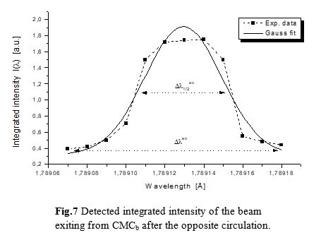
The experimentally determined spectral width of the exiting beam amounts to:
Dlex=(10±0,5)·10-5Å (DEex=0,5 eV)
with the width at half height of the peak fitted by different functions:
Dl1/2ex = 4,7·10-5Å (DE1/2ex=0,15 eV) (Gaussian)
Dl1/2 ex = 5,0·10-5Å (DE1/2ex=0,19 eV) (Int.area)
Dl1/2 ex = 5,8·10-5Å (DE1/2ex=0,23 eV) (Lorentzian)
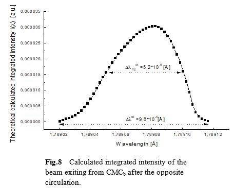
These detected spectral widths are in good agreement with the theoretically obtained values Dlth=9,6·10-5Å and Dl1/2th= 5,2·10-5Å, respectively (Fig.8). The energy resolution of this CMC amounts to DE/E=2,5·10-5. The spectral shift dl=0,5·10-4Å, which is corresponding to dE»0,19eV on the axes of wavelengths in Fig.7 and Fig.8 is within the accuracy of calibration (absorption edge of CuKa line) of the monochromator in RÖMO1.
Conclusions and Applications
Presented studies show that monochromatization with very narrow spectral width can be achieved using XRs and CMCs. The beams formed in CMC can change the degree of temporal and spatial coherence and have very high polarization coefficient. These kinds of designs have several advantages:
· thermal stability of the cavity due to the ideal thermal contact between the operating parts;
· perfect orientation of reflecting planes in the operation;
· lack of Laue- and Bragg-case mixed reflections;
· stable reflection geometry, ensuring the beam circulation in the same plane;
· no loss of energy due to the polarization.
Besides the generally discussed application of X-ray resonators, the optical properties of XRs or CMCs are important also from another point of view. There are many situations where a highly monochromatic beam at one fixed wavelength is required. Such situations are common when X-ray excitation of some physical process is necessary. Taking into account of XR’s and CMC’s properties of X-ray wave monochromatization around its specific wavelength and collimation, they could find their use also in different fields of coherent X-ray optics. Further analyses are in progress which can hopefully lead to a new designs of closed loop X-ray resonators with new suggestions of the beam in and out coupling.
Acknowledgments
The author is grateful to the Deutsches Elektronen Synchrotron for hospitality during his scientific visit and providing facilities to do the investigations in DESY/HASYLAB (Hamburg, Germany) and to his uncle: Dr. Armand Rostomyan (Yerevan State University, Armenia) for many helpful discussions.
References
[1] W.L.Bond, M.A.Dugyay, P.M.Rentzepis, Proposed resonator for an X-ray laser, Appl.Phys.Letters, v.10, 216-218, 1967.
[2] R.D.Deslattes, X-ray monochromators and resonators from single crystals, Appl.Phys.Letters, v.12, 133-135, 1968.
[3] R.M.J.Cotterill, A universal planar X-ray resonator, Appl.Phys.Letters, v.12, 403-404, 1968.
[4] A.V.Kolpakov, R.N.Kuzmin, V.M.Ryaboy, Some characteristics of the resonators for X-ray frequencies, J. Appl.Phys., v.41, 3549-3550, (1970).
[5] R.M.J.Cotterill, Universal planar X-ray resonator, No.3518427 (USA-Patent),
United States Patent Office, 1970.
[6] A.M.Jacobs, E.S.Keny, Enhancement and control of radiation beams by vibrating media, No.3832562 (USA-Patent), United States Patent Office, 1974.
[7] J.Bremer, L.Kaihola, An X-ray resonator based on successive reflections of a surface wave, Appl.Phys.Lett., v.37(4), 360-362, 1980.
[8] A.H.Rostomyan, P.H.Bezirganyan, X-rays and gamma-rays autofocusing, Dokl.Akad.Nauk. Arm.SSR, v.64, 228-234, 1977.
[9] A.H.Rostomyan, P.H.Bezirganyan, Realization of X-rays and gamma-rays autofocusing, Dokl.Akad.Nauk. SSSR, v.238, 73-76, 1978.
[10] A.H.Rostomyan, P.H.Bezirganyan, Tuning and determination of the degree of monochromatization and collimation in X-ray focusing resonators,
Acta Cryst., v.A34, 240, 1978.
[11] A.H.Rostomyan, P.H.Bezirganyan, Monochromator for X-Ray Radiation, No.714506
(USSR-Patent), 1977.
[12] A.H.Rostomyan, P.H.Bezirganyan, A.M.Rostomyan, X-Ray Resonators. I-Theory,
Phys.Stat.Sol. (a), v.116, 483-491, 1989.
[13] A.M.Rostomyan, A.H.Rostomyan, P.H.Bezirganyan, X-Ray Resonators.
II-Calculation and Experiment, Phys.Stat.Sol. (a), v.116, 493-502, 1989.
[14] A.H.Rostomyan, A.M.Rostomyan, X-Ray Resonators. III-Application,
Phys.Stat.Sol. (a), v.126, 29-39, 1991.
[15] M.Hart, T.Koga, Yu.Takano, Mixing symmetric and oblique Bragg reflections in rigid channel-cut crystals, J.Appl.Cryst., v.28, 568-570, 1995.
[16] A.M.Rostomyan, J.Wuerges, W.Graeff, G.Materlik, Cyclic X-ray monolithic high resolution focusing monochromators, Deutsches Elektronen-Synchrotron DESY, Hamburger Synchrotronstrahlungslabor HASYLAB, Annual Report Part-I, 995-996, 1997.
[17] R.Caciuffo, S.Melone, F.Rustichelli, A.Boeuf, Monochromators for X-ray Synchrotron radiation, Physics Reports (Review Section of Physics Letters) 152, No.1, 1-71, 1987, North-Holland, Amsterdam.
[18] M.Renninger, Z. Naturforsch. v.160, 1110, 1961.
[19] K.Kohra, J.Phys.Soc.Japan, v.17, 589, 1962.
[20] A.H.Rostomyan, A.M.Rostomyan, Integral power and intensity of the beam from an
X-ray resonator, J.of Contemp.Phys., v.28, N.5, 19-25, 1993.